First off if anyone has any questions, email me with welder in the subject line and I will try to get back to you
tkramer at sherlocktk.com
How to make a mig welder that uses 2 car
batteries (24v). This also takes the welder from its 90amp rating and puts it
more in the 200amp range, allowing for much thicker steel to be welded. Here is the how to. Total cost was around
150, but only cost me around 50 as I consider the welder free. This is
basically the same system as ready welder but without the cost. I have to say I
take NO liability for providing this information. Its
just me screwing around with an idea I had and this one worked. I am sure there are things to be done to make
this “safer” but
it being less than 30v there is little risk.
Parts List:
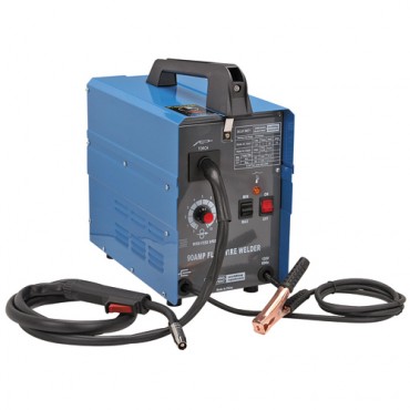
1. Harbor freight 90 amp Flux core welder. This was my first welder, but it had
outlived its usefulness as I got a better (more amperage) machine. Frequently
on sale for $90
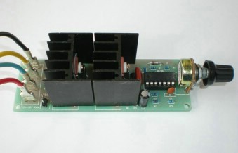
2. PWM (Pulse Width Modulation) 24v motor speed control ($25) – ebay (needs to be rated at least 2 amps. Motor pulls .68 amps on my welder, then 3x safety/engineering margin) Mine is rated at 20 amps because I had no idea at the time. A resistive type of speed control like used in RC cars would also work. But I wanted more functionality and adjustability.
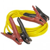
3. Jumper Cables ($15) - 8 ga seems to not get hot at all.
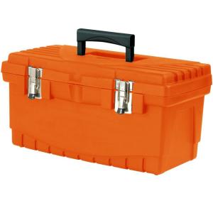
4. Plastic Home Depot tool Box ($8) (purposely wanted it to look cheap)
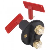
5. Battery Disconnect Switch ($4)
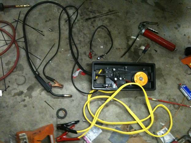
Step 1. Take out the "guts" from the harbor freight welder. The only parts you want are the ground cable, Torch cable, Wire feed motor assembly and the thing that holds the spool of wire. I don’t have a picture of the gutted welder. Sorry no pic of this stage, It was still prototype
Step 2. Take out the Top plate in the welder that all of the above items and attach into a box of your liking. I used a 8 dollar home depot tool box as seen above. I cut out the handle part and screwed the metal plate from the mig welder into it to hold all of the items.

Step 3. Install Battery cutoff switch in appropriate position. This allows me to turn off and on the welder without needing to mess with the jumper cables. See it between the circuit board and the flux core welder above with the red handle
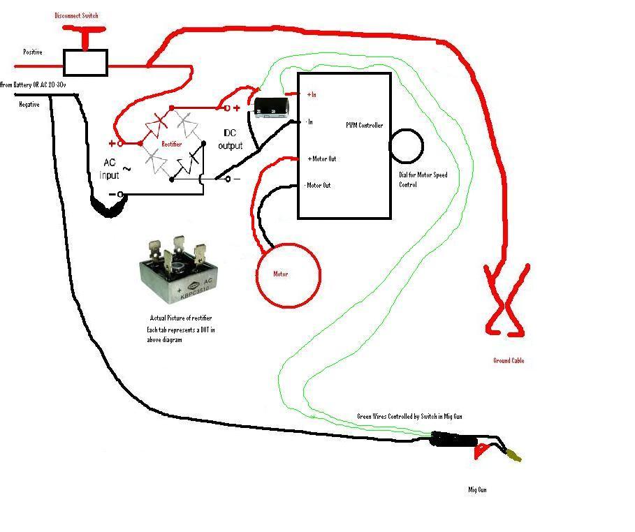
Step 4. Install PWM speed control so you can access the knob which will allow wire feed speed. Refer to below diagram(s) for how to do it.
Step 5. Attach the welding "ground" to the
Positive Connection on the battery, Attach the mig
gun to the negative battery connection. via the jumper
cables. Refer to below diagram(s) for how to do it.
The Electrical Diagram

Bottom View of plate which hold wire advance and bottom view of battery disconnect switch
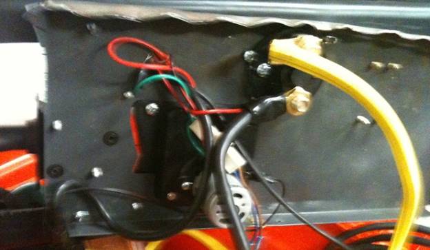
Step 6. Tidy up the wiring and affix everything that
looks like it needs to be tied down.
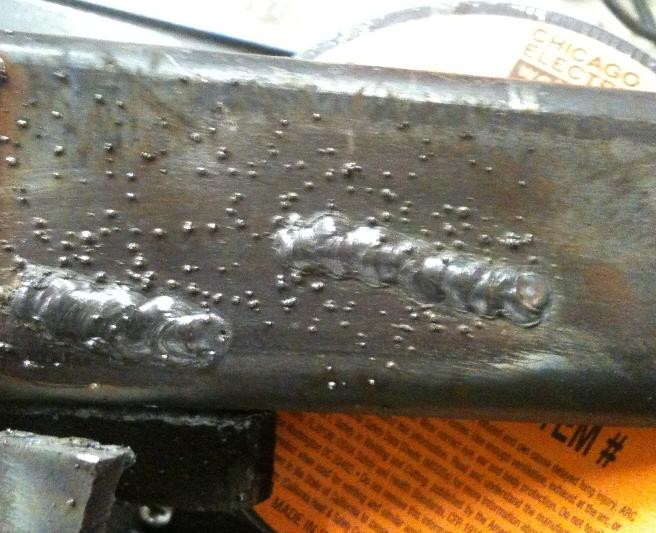
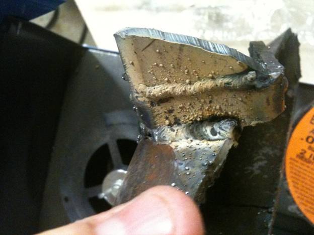
Hook up the batteries, and turn the speed control to about 20 % and run
a test bead. The picture shows .030 wire, I have since tested .035 and liked the results even
better, but either work ok. The below
pictures are done on 3/16 steel. Much
better penetration than the AC version of this welder as the amperage delivered
from the batteries greately exceeds what 120v power
can provide.
Wirebrushed welds 3/16 steel.
Non-wirebrushed welds same 3/16 steel.
Step 7. Put you goggles, Gloves and all the
appropriate cables (I put my 4 1/2 grinder) in the tool box for your
"welding kit" It all fit in nicely.
Optional: I thought about just putting terminals to hook normal jumper cables
to, but I really did not like the idea of having to pull the welder around and
have a cable short out somehow. I opted for the dedicated cables, but it would
be easy to do some type of high current connectors I suppose. This would take
away some of the bulky wiring. I would also consider a better ground clamp. The
one from Harbor freight gets very hot, but the harbor freight mig gun does not seem to heat up.
Addendum:
Diagram on how to make it a "cold tip" welder. Here I utilize a 24v
starter relay. It should have enough current capacity. I have not tested this
configuration, but I am confident it will work. The most important factor is to
get a starter relay that is sized appropriately to handle the current.
I learned to weld with the hot tip, so even on my cold tip welder I really do
not miss that feature. My mind is now hard wired on how to use the hot tip.

Super Advanced: For persons wishing to use both transformer and DC current source. If you do this please make sure its done safely by making the high voltages not be exposed to contact.
Basically you hook your jumper cable to the
transformer or the car batteries. This
is probably not a very safe configuration so I don’t recommend it but someone
asked me how to do it.
With the addition of a rectifier you can eliminate the stock wire speed
controller and use the PWM controller exclusively. (see
above diagram)
The only thing I am not sure about is how large of a capacitor. I am not enough
of a EE to help with that. I would just put in a big
one and see if it works. (like 1000mf) Many rectifiers
are rated for 10 amps or so so this is not an issue.
The capicator is there for filtering of the incoming
power to generate a more smooth DC current. The rectifier can take either an AC
or DC input. The welder will output a AC arc when on
AC power and a DC arc when on DC power
When you are at home, hook jumper cables to transformer leads The polarity does
not matter. When on the trail hook to the 2 batteries (Polarity matters). It
all works the same.